


MGT6000 Doppelwelle
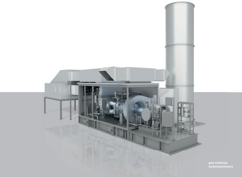
Jahrzehntelange Erfahrung mit Industriegasturbinen
und tiefgreifende Anwendungskenntnisse
haben zu einer Weiterentwicklung
kleiner Industriegasturbinen geführt – der
MGT-Familie.
Die Doppelwellen-Gasturbine MGT6000
wurde für mechanische Antriebsanwendungen
entwickelt – geeignet für alle Kundenanforderungen innerhalb eines
modularen
Paketdesigns.
Benefi ts at a glance
– Modular design for easy
and fast installation
– High effi ciency
– Low emissions
– Low operating costs
– Low life cycle costs
Typical applications
Twin shaft gas turbines have a
variable speed drive shaft which is
the best and most effi cient way not
only to control fl ow or discharge
pressure, but also to start a
mechanical drive train. Driven units
are compressors and pumps for
pressure increase and transport of
gaseous and liquid media.
Typical application fi elds are
midstream and upstream oil & gas
production sites operating mainly
in simple cycle mode.
Gas turbines of twin shaft design are
also used for power generation at
fi xed speed. Selection criteria in such
cases are e.g. the package design or
driver communality in combination
with mechanical drive units.
Gas turbine
– Heavy duty, twin shaft
– 11 stage air compressor
– 6 combustion chambers
multi-can, ACC1) combustors
– 2 stage high pressure turbine
– 2 stage power turbine
Integrated auxiliary gear
– Parallel shaft gear type
– Drive for main lube oil pump
– Torque transmission of electric
starter motor for gas turbine
start-up
Driven unit
– Compressors for midstream
applications (gas transportation &
storage)
– Compressors for upstream
applications (gas gathering, gas
reinjection, etc.)
– Pumps
– Electric generators for power
generation
Gas turbine package
– Package for outdoor installation
– Noise emission
- All equipment is designed for
LpA = 85 dB(A) measured in 1 m
distance and 1.5 m height
- LpA = 802), 752), 702) dB(A)
– Base frame
- With integrated lube oil and fuel
system
– Starting system
- Variable frequency drive for gas
turbine starter motor
– Integrated lube oil system
- Main lube oil pump driven via
auxiliary gear
- Stand-by lube oil pump
(AC-motor driven)
- Emergency lube oil pump
(DC motor driven)
- Air to oil cooler (free standing)
- Water cooler2)
- Integrated lube oil tank
- Lube oil tank heater
- Lube oil filter
- Control valves
- Oil mist separator
– Fuel system
- Fuel gas system
- Double block and bleed valves
- Control valves
- Dual fuel system2)
– Air inlet system
- Table type filter house with depth
loading cartridges
- Filtration class:
Pre-filter: G4,
Fine-filter: F9 (E112))
- Static filter2) with anti-icing2)
- Pulse type filter in table or down
flow arrangement2)
– Exhaust system
- Transition duct
- Expansion joint
- Free standing stack
– Enclosure
- Gas turbine enclosure for outdoor
installation
- Fire detection and CO2
fire-fighting system
- Water-mist fire-fighting system2)
- Gas leakage detection
- Maintenance cranes
– Turbine compressor cleaning system
- Offline and online washing
- Mobile wash trolley2)
Controls
– For installation in air conditioned
control room (to be provided by
others)
– Gas turbine control system
- Gas turbine control & protection
- Unit sequencing
- Human machine interface (HMI)
- Alarm management
– Compressor control (if applicable)
- Anti-surge controler
- Performance controler
- Load sharing2)
– Low voltage distribution system
- AC power supply for all electrical
consumers
– Turbine starting system
- Variable frequency drive (VFD)
– Uninterrupted power supply system
- Buffered with batteries
- DC supply for emergency lube oil
pump
- AC supply for all electrical panels
– Data storage system
- Long term data archive
- Event logger
– Plant control system interface
- Modbus TCP interface
- Others optional
Documentation
– Engineering documents
– Installation manual
– Operating instructions
– Quality documentation
Factory acceptance test of turbine
– Core engine
ASME PTC-22
Other tests2)
– According to API requirements