


MGT6000 Einzelwelle
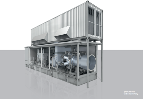
Vorteile auf einen Blick
– Modulares Design für einfache und schnelle Installation
– Hohe Effizienz
– Geringe Emissionen
– Geringe Betriebskosten
– Geringe Lebenszykluskosten
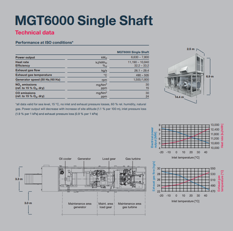
Typical applications
Gas turbine generator units are
operated for e.g. emergency and
black start applications, on off-shore
platforms (with adapted package
design) mainly in simple cycle
mode.
For CHP1) applications (most common)
gas turbine generator units are
operated in combination with a heat
recovery unit for different heat
processes, resulting in e.g.
– Power, Steam Generation
– Power, Hot Water Generation
– Power, Steam & Chilled Water
– Power, Steam & Hot Water
CHP applications are beneficial for
various industries such as food
processing, pulp & paper, breweries,
automotive, etc. having demand for
Heat and Power.
CHP processes provide increased
efficiencies and reduced CO2
emissions compared to conventional
power & heat generation.
Overall CHP efficiencies reach 90%
and higher depending on the heat
process.
Gas turbine
– Heavy duty, single shaft
– 11 stage air compressor
– 6 combustion chambers
multi-can, ACC2) combustors
– 3 stage turbine
Load gear
– Planetary gear type
– Speed reduction to 1,500 rpm (for
50Hz) or 1,800 rpms (for 60Hz)3)
– Drive for main lube oil pump
– Torque transmission of electric
starter motor for gas turbine
start-up
Generator
– 4 pole, 3 phase, synchronous
generator with built-in exciter,
rotating rectifier and permanent
magnet pilot generator (PMG)
– Direct air cooled
– Insulation class F / temperature
rise class B
Controls
– All electrical cabinets installed on
skid in air-conditioned control
compartment
– Gas turbine control system
- Gas turbine control & protection
- Unit sequencing
- Human machine interface (HMI)
- Alarm management
– Generator control & protection
system
- Automatic synchronization
- Automatic voltage regulator (AVR)
- Generator protection relay
– Low voltage distribution system
- AC power supply for all electrical
consumers
– Turbine starting system
- Variable frequency drive (VFD)
– Uninteruptable power supply
system
- Buffered with batteries
- DC supply for emergency lube oil
pump
- AC supply for electrical panels
– Data storage system
- Long term data archive
- Event logger
– Plant control system interface
- Modbus TCP interface
- Others optional
Documentation
– Engineering documents
– Installation manual
– Operating instructions
– Quality documentation
Factory acceptance test of turbine
– Core engine
full-speed, full-load
Complete unit test3)
– Full-speed, full-load
– Full-speed, no-load
Package
– Fully-integrated for outdoor
installation
– Noise emission
- All equipment is designed for
LpA = 85 dB(A) measured in 1 m
distance and 1.5 m height
- LpA = 803), 753), 703) dB(A)
– Single-lift base frame
- With integrated lube oil and
fuel system
– Starting system
- Variable frequency drive for gas
turbine starter motor
– Integrated lube oil system
- Main lube oil pump driven via
load gear
- Standby lube oil pump
(AC motor driven)
- Emergency lube oil pump
(DC motor driven)
- Water to oil cooler
- Air to oil cooler3) (free standing)
- Integrated lube oil tank
- Lube oil tank heater
- Lube oil filter
- Control valves
- Oil mist separator
– Fuel system
- Fuel gas system
- Double block and bleed valves
- Control valves
- Dual fuel system3)
– Air inlet system
- Static depth loading cartridges
- Filtration class:
Pre-filter: G4,
Fine-filter: F9 (E113))
- Static filter3) with anti-icing3)
- Free standing filter house3)
– Exhaust system
- Transition duct up to interface at
enclosure for connection to optional
downstream exhaust system
– Enclosure
- Complete package for outdoor
installation
- Fire detection and CO2
fire-fighting system
- Water-mist fire-fighting system3)
- Gas leakage detection
- Maintenance cranes
– Turbine compressor cleaning system
- Offline and online washing
- Mobile wash trolley3)