Clearance control is of great importance to turbomachine designers and is necessary to ensure today’s performance, efficiency and operating life. Excessive clearances result in loss of cycle efficiency, flow instability and hot gas entering the disk cavity. Insufficient clearances restrict coolant flow and cause abrasion of contact surfaces, overheating of lower components and surface damage that limits component life. Specialists pay close attention to gap control because it is often the most cost-effective method of improving system performance.
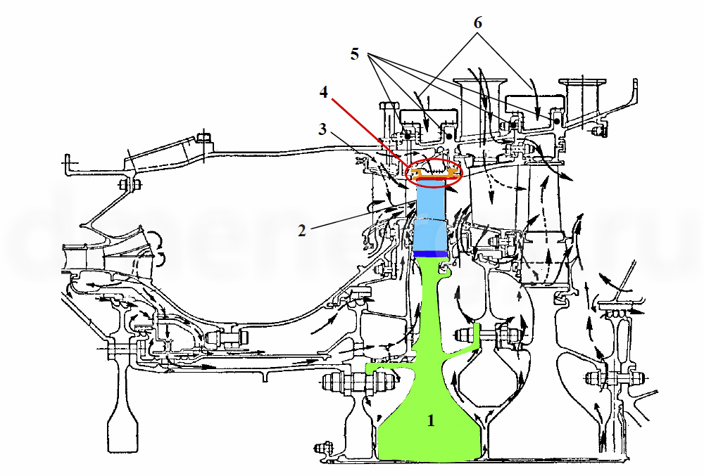
The key compressor and turbine seal locations in an industrial engine are shown in the figure 1.

- Wearable compressor seals
- Wearable turbine seals
- Brush or abradable seals between stages
- Labyrinth bearing seals
- High pressure brush lip seal
Mechanical seal
Radial, mechanical and radial-torque seals are used to minimize leakage between rotors and housings. Seals of movable joints used in gas turbine equipment can be divided into non-contact (slotted) and contact seals. The main ones are presented in Table 1.
Table 1 – Seals of movable joints
| Class | Seal type | Sealing pattern (clearance in mm) | Limitations | Effective clearance, µm | ||
| sliding speed | temperature | pressure | ||||
| Non-contact | Labyrinth |  |
no limitation | 1200 and more | no limitation | 50… 200 |
| Brush |  |
400 | 1000 | 1,2 per one row of brushes | 40…165 | |
| Graphite non-contact |  |
180 | 700 | 25 | 3…12 | |
| Contact | Graphite contact |  |
100 | 700 | P*V=50
MPa-m/s |
10…20 |
| Piston rings, metal packing |  |
80… 100 | 700 | P*V=50
MPa-m/s |
10…20 | |
| Lapped pairs, soft packing glands. |  |
3 | Lapped pairs 20…500 oil seals 363…343 |
500 | 0 | |
| Cuffs (leather, rubber) | ") |
1 | 310 | 600 (several cuffs) | 0 | |
Blade Face Sealing
Turbine blade face sealing is a challenging problem due to high speed, temperature and varying clearance.
Research is ongoing, the main element of which is the development of a seal with improved blade face clearance control.
- High Pressure Turbine Disk (HPT)
- HPT blades
- Inlet air
- HPT blade end seal
- Flanges
- Inlet air
Figure 2 – Location of the TVD blade end seal of a modern gas turbine
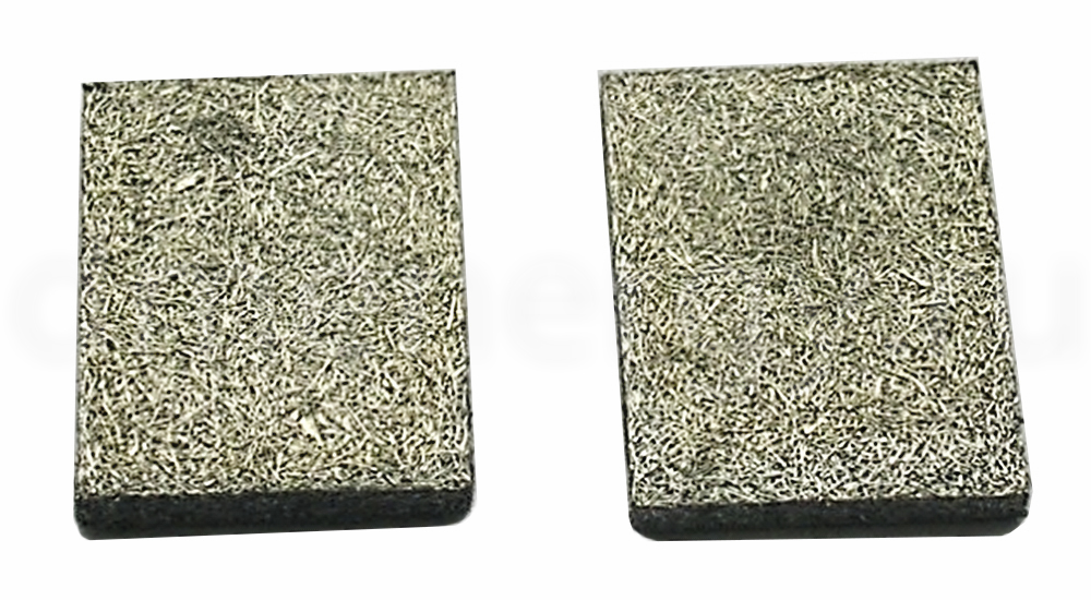
Abradable sealing materials
As the name implies, abradable sealing materials abrade as they rotate, causing blades to form during operation. They are used to join compressor, gas and steam turbine housings to control clearances to levels that are difficult to achieve by mechanical means. Erasable seals provide a good distribution in gas turbines as, for example, a simple means for basic gas path clearances in both compressor and turbine.
The most effective materials as abradable elements are metal fiber based electrode materials.