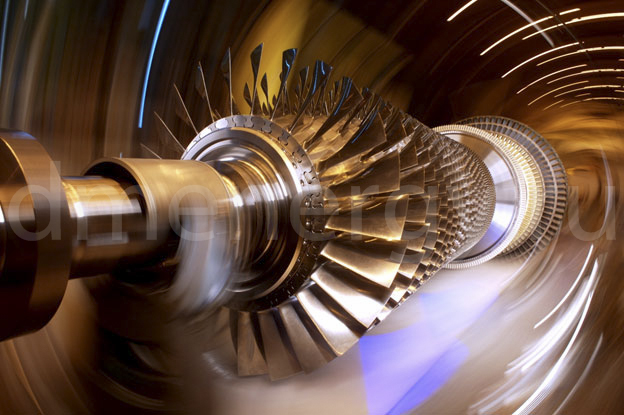
A gas turbine plant is a complex technical device that converts chemical energy of fossil fuel into mechanical energy to drive various devices such as electric generators, pumps, compressors.
Gas turbines are widely used in the electric power industry, oil and gas industry, manufacturing.
In the classical understanding, a gas turbine consists of 3 part – compressor, combustion chamber and turbine. The compressor compresses air and feeds it into the combustion chamber. In the combustion chamber the process of mixing fuel with air and combustion of the fuel-air mixture takes place. The flow of hot gases hits the turbine and makes it rotate.

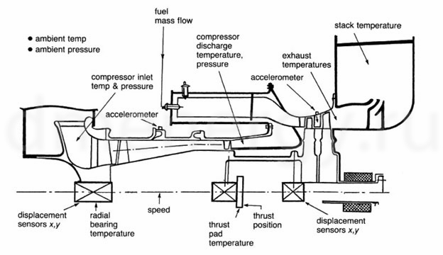
A gas turbine is a fairly complex operating system of various mechanical components that operate at high speeds and high temperatures. In order for the installation to benefit and maintenance costs to be minimized, monitoring systems should be used to identify problematic components. Such systems can help avoid significant turbine damage and minimize maintenance costs.
GE’s Bently Nevada product line has been synonymous with equipment protection and monitoring for more than 50 years. A network of global experts is dedicated to helping customers solve the most challenging problems in a variety of industries. From refineries and petrochemical plants to hydroelectric facilities and wind farms, GE Bently Nevada systems offer reliable and proven equipment monitoring and a comprehensive portfolio of services.
Main units of gas turbine monitoring and diagnostics
| No. n/a | Node/type of measurement | Type of measuring device | Location/node | Type of measuring system/module |
| 1 | Radial vibrations of GTU rotor | Proximity probes ( proximity sensors ) | Face or bearing support part | 3500/42 or 3701/40 |
| 2 | Vibrations of bearing housings | High temperature seismic (high temperature seismic probes) | Bearing housing | 3500/42 or 3701/40 |
| 3 | Rotor position in axial direction | Proximity probes ( proximity sensors ) | Mounted parallel to the rotor at a maximum distance of 16 mm. | 3500/42 или 3701/40 |
| 4 | Rotor vibrations in axial direction | Proximity probes ( proximity sensors ) | Installed in thrust bearing for stress diagnostics | 3500/42 или 3701/40 |
| 5 | Combustion dynamics in the combustion chamber | High temperature dynamic pressure sensor (high temperature dynamic pressure sensor) | Installed in both annular and tubular-ring combustion chambers (in each flame tube). | 3500/64 or 3701/40 or 3701/44 |
| 6 | “Ring” temperature in bearings | RTD/TC | 2 measurement points in the lower and upper bearing housings | 3500/60 or 3500/61 |
| 7 | “Longitudinal” temperature in bearings | RTD/TC | 4 measuring points in bearing housing | 3500/60 or 3500/61 |
| 8 | Time signals during synchronization | Proximity probes ( proximity sensors ) | Physical status of rotor speed and vibration phase | 3500/25 or 3701/40 |
| 9 | Exhaust gas temperature | RTD/TC | Minimum 1 measuring point | 3500/60 or 3500/61 |
| 10 | Lubricating oil supply | RTD/TC | Installed in each oil supply line | 3500/60 or 3500/61 |
| 11 | Lubricating oil temperature | RTD/TC | Minimum 1 measuring point per line | 3500/60 or 3500/61 |
| 12 | Tachometer | Proximity probes ( proximity sensors ) | Rotor speed measurement | 3500/50 or 3701/40 |
| 13 | Blade condition | Magnetic pickup (magnetic pickup) | Measurement of GTU blades service life | 3701/68 |
| 14 | Excess speed | Proximity probes or magnetic pickups | 3 measurement points for rotor speed overrun detection | 3500/53 or 3701/55 |


